Personal Earth Station
Contents
|
|
Topic
|
Page No. |
|
|
|
|
Introduction
|
3 |
|
|
PES
Cards Identification |
7 |
|
|
PES – Normal Operation |
10 |
|
|
|
Operating modes
|
|
|
|
Normal Mode |
12 |
|
|
Installation Mode |
12 |
|
|
Ranging Mode |
13 |
|
|
Diagnostic Mode |
14 |
|
LED
– Display List |
14 |
|
|
|
Remote Port card LED Codes |
15 |
|
|
Normal Startup Sequence |
15 |
|
|
|
|
|
|
|
|
|
|
|
|
|
|
|
|
|
|
|
|
|
|
|
|
|
|
|
|
1. Introduction:-
The Personal Earth Station (PES) is a
complete data and voice telecommunications terminal supporting two-way access
via satellite to centralized computer and telephone exchange facilities. In
addition, some models of the PES can also receive video signals when equipped
with an optional satellite television signal receiver.
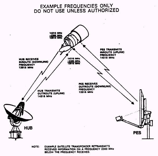
Given below is a typical link from
Earth station to the VSAT.
The PES-8000 Indoor Unit front and back view are show on the
next page.
INDOOR UNIT: The 7-1/4" high PES Model 8000 indoor unit has a front panel
nameplate reading: PERSONAL EARTH
STATIONTM
. Note that the nameplate does not include the letters "DIU/O." The rear panel is marked with the 8000 model number.
OUTDOOR EQUIPMENT: RF Unit, with 1.0M, 1.2M, 1.8M, or 2.4M quick repoint antenna. For sites
designated for video reception, as a general rule the antenna is 1.8M or
larger. The Outdoor Equipment is shown on the next page.


2. PES CIRCUIT CARD IDENTIFICATION: -
PES 8000 indoor units provide port
card slots. Generally, these port cards provide the interface to customer data
or voice equipment.
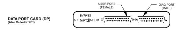
DATA PORT CARDS (DP)
The DP provides the interface to the
user’s digital equipment. The DP card provides a single RS-232 serial data port
interface. The Hub downloads software to the DP for the specific digital
communications protocol required.


TURBO PORT
CARD (TP)

The TP also provides interface to the user’s digital equipment and
has two or four serial data communications links. Two of these ports are always
RS-232 (built-in PLC). The next two data ports (plug-in PLC) may have the
following
interface standard: RS-232, modem backup style RS-232, V.35,
RS-422 or other standards or capabilities as developed.

PES MODEL OR TYPE SPECIFIC CIRCUIT CARDS
The signal the PES receives from the
satellite must be down converted, demodulated, and decoded. In addition, the
PES must achieve receive synchronization with the signal. The PES must
determine the proper timing for the transmit signal and must encode and
modulate signal to be transmitted.
INTERMEDIATE FREQUENCY MODULE (IFM)
The intermediate frequency module
(IFM) accepts the received mixed
outroute and video signals from the RF Unit, tunes to the appropriate receive
frequency, down converts the signal, if necessary despreads the signal
(required for the spread Quietroute signal),demodulates and decodes the
outroute signal, and sends the processed results to the IOC chip on backplane.
The IFM provides transmit filtering and modulation of the transmit signal. The
IFM also provides monitor and control functions for the PES including an
interface for the site commissioning computer (CONFIG connector), storage of
commissioning parameters in EEPROM, and LED display of PES status.
3. PES - NORMAL OPERATION
GENERAL
The PES is designed for unattended
operation, and once installed, tested, and initially started, no operator
action is required under normal conditions. Except for servicing, indoor power
should remain on at all times.
The RF Unit has no controls or
indicators. The RF Unit health and status is displayed on the indoor unit LEDs.
The PES Model X000 series indoor unit does have controls and indicators, but
these do not require attention during normal operation.
The indoor unit power switch should
remain on at all times during normal operation.
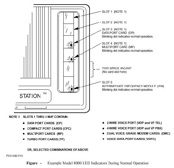
If the system is fully operational and
running without any errors, the IFM
displays an alternating BLANK/BLANK.
([ ]/[ .]) status (looks like a flashing decimal point).
All the port cards after proper boot
up will give BLANK/BLANK display also.
The normal boot up sequence for the
port cards(viz. TPC & VDPC) is given below in details.
OPERATING MODES
The operational modes are: normal
mode, installation mode, (COMM) ranging mode, and diagnose mode.
NORMAL MODE
In normal mode, the PES goes through
the steps necessary so that the remote may carry traffic across the spacelink.
Those steps are as follows:
·
Startup
Initialization - the PES performs startup self tests, initializes hardware and
communications links.
·
Outroute
Acquisition - PES performs the processing required to find and begin receiving
the outroute.
·
Transmit
Frequency Lock - the PES performs the processing required to precisely tune the
transmit frequency. The PES does not allow port card transmission until
frequency lock is obtained.
·
Outroute
Tracking - the PES receives the outroute and transmits inroute bursts on port
card command. The PES transmits overhead and traffic bursts set at a
"Ranged Power Level" and a "Ranged Timing Offset."
INSTALLATION MODE
In INSTALLATION mode, the PES goes
through startup initialization and sets its spacelink receive equipment to
receive on the programmed primary outroute frequency previously configured into
the indoor unit. During installation mode the IFM LED state code is [1]. Installation mode provides an
antenna-pointing signal (10 volts to 0 volts) at the RF Unit. An installer uses
a voltmeter to observe this signal while refining the antenna aiming
adjustment. Lower readings on the voltmeter indicate a strongly received
signal. Specifically, a reading of:
·
5.0 to 10.0 volts indicates that the demodulator has not
acquired the outroute. The voltage reading corresponds to the overall receive
signal strength and is a function of the receive demodulator’s AGC value. A
larger value indicates a higher AGC level, indicating a weaker outroute signal.
· 0.0 to 5.0 volts indicates that the demodulator has acquired the outroute. The voltage reading corresponds basically to the receive signal strength and is a function of the Eb /No (energy per bit to noise energy ratio). An Eb /No of 5.0 dB or less indicates a mediocre signal which is Displayed as a 5.0-volt reading. An Eb /No of 12.0 dB (or higher) indicates a high quality signal. The AGC v the demodulator acquires the signal, providing a clear indication of the remote’s receive status. The antenna pointing output is decreased about 0.4 volts per dB of signal strength (an antenna pointing output reading of 2.2 volts, for instance, indicates an Eb /No of 12 dB).
alue never actually reaches a 5.0-volt reading; the meter will jump when the
antenna pointing is refined so that the signal is minimized (less than 3 volts, for example), it indicates that:
·
The
PES receiver has locked onto an outroute.
·
The
Ebi
/No
reading is at the highest value that can be attained by adjusting antenna
pointing.
COMM (RANGING) MODE
The COMM (ranging) mode causes the PES
to transmit ranging bursts which start at an "Initial Power Level"
and an "Initial Timing Offset." An automatic process (automated
ranging) or the Hub operator (manual ranging) measures the power and timing of
these bursts as they arrive at the Hub. During ranging, adjustments are made to
the transmit burst power and timing.
DIAGNOSE MODE
In the diagnose mode, a remote runs
through an expanded set of self tests once and displays the results on the IFM
seven segment LED. An installer typically puts a remote in diagnose mode to
enter the site commissioning parameters with the portable computer, because a
remote does not transmit while in diagnose mode.
IFM AUTO COMM - RECESSED SWITCH
The recessed AUTO COMM switch on the
rear of the IFM is for customer use immediately after the antenna is repointed
to a new satellite in an emergency repoint situation. Pressing the recessed
switch using a toothpick or similar object interrupts data traffic and places
the PES in COMM (ranging) mode, initiating a 10- to 30-minute autocommissioning
ranging session which adjusts the site’s PES transmit power and timing for the
new satellite. When the adjustments are finished, the port card display is [3]/[b.]. Pressing the recessed switch again returns the PES to normal
mode. Do not press the recessed switch
during normal installation commissioning. Instead, use the DIU Configuration
Editor SWITCH function to select the desired PES mode including COMM (ranging)
mode when needed.
4. LED DISPLAY LIST
During normal operation for PES model X000 series, the indoor
unit LED indication for the IFM, and port cards is a blank alternating with a
blank dot. This indication looks like blinking decimal points, [BLANK]/[BLANK.]. When these normal indications are present, the PES is
receiving the proper outroute signal from the Hub and is ready to transmit (or
is transmitting) inroute signals to the Hub. When the PES is in other than
normal operation (such as being reset, under self-test, in diagnose mode, in
installation mode, in alarm mode, or other states
and conditions), the LED displays change from [BLANK]/[BLANK.] to an alphanumeric code. These alphanumeric codes are
indicative of PES and network conditions, and thus provide troubleshooting
information.
REMOTE
PORT CARD LED CODES

NORMAL
STARTUP SEQUENCE
As the PES is switched ON , the following displays are seen
on the 7-segment display of the PORT CARDS.
·
LED
spinning pattern - LED test.
·
1/2. - Port card is waiting for a poll from
the IOC/IFM
·
8/2. - 8/4. - Port card is waiting to get into
outroute sync. 8/4. indicates that a superframe header is being received, and
regression to 8/2. indicates that the superframe header did not have the right
carrier ID number.
·
8/E. - Port card is waiting for a broadcast
of the RAM boot code from the hub. The broadcast occurs automatically (at time
intervals configurable from the hub), or it can be forced via the VOC DLL CNTRL
screen.
·
8/F. - Port card is receiving RAM boot code
packets. This broadcast lasts about 15-20 seconds.
·
8/blank. - Port card received some RAM boot
code packets but then quit receiving them. This comes up only if a packet was
missed during the broadcast or the remote just got in sync during a broadcast
and so missed some of the first packets. The card will wait for the broadcast
again, and then will transition to 8/F. to receive the missed packets before proceeding
to 5/h.
·
5/h. - Remote waits here until an RRD is
received confirming the RAM boot code version.
·
7/1. - When a HIAM response is received,
the port card progresses to this state and waits for 15 seconds or until
network parameters are received. The
network
parameters broadcast occurs automatically (at time intervals configurable from
the hub), or it can be forced via the
VOC DLL CNTRL
screen.
·
5/6. - Remote may wait here for a minute or
so for the transmit phase lock loop to lock up.
·
5/8. - 5/9. - Card waits here to transmit HIAM
messages to the hub.
·
7/2. - 7/3. - Port card is transmitting a code
request to the hub.
·
7/4. - Port card is
receiving user code packets. If not all are received, the port card will eventually
go back to 7/2.
·
blank/blank. - Online state, user
code is running
Please note that after booting, the Port Cards will show a
display of BLANK/BLANK.
If any abnormal displays are seen, then the user will have
to contact Central HUB for online help.